Getting my ZX Spectrum Next onto Wifi and the Internet, plus Pi Zero Accelerator
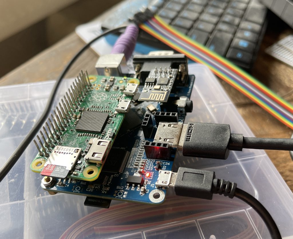
I’m enjoying my Xberry Pi ZX Spectrum Next, but I have to say the ‘simple’ upgrade of getting it onto Wifi via the cheap and cheerful ESP 8266 was not fun.
While I had every intention of setting up my Speccy keyboard on the board’s matrix connector, I need to wait for a socket of the correct pitch. It turns out the Xberry Pi needs 0.2mm spacing and I have none in my parts box. Instead I figured do the other main upgrades, namely add a Pi Zero “accelerator” and the Wifi upgrade.
ZX Next Pi Zero Accelerator Upgrade
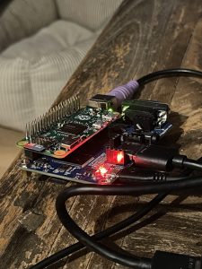
Fully expecting the Pi Zero to be the thing that caused me trouble, I was shocked that not only my soldering had gone perfectly but also the flashing of the SD card.
So many community members had advised to use a highly specific Pi Zero, I thought my spare board would be wrong. But it worked first time!
My pin header made the soldering trickier than usual, maybe it soaked a lot of heat? Just remember the header needs to go on the ‘wrong’ side and take your time.
The Pi Zero upgrade is hardly used currently but the ZX Next team keep hinting at future utility, and at least one game is in development that uses it as a kind of math coprocessor.
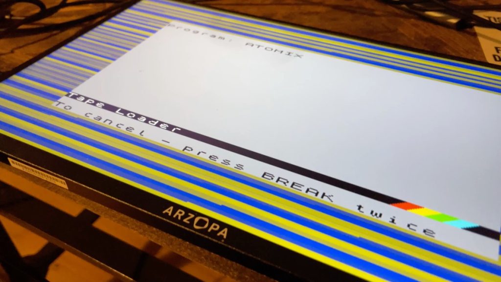
So after running a TZX file and some SID tunes, I moved on to the ESP figuring I would have everything done quick as a flash. Pardon the pun.
Adding Wifi to the Next
The Next can come with Wifi already installed apparently, and some Xberry bundles come with one as standard, but the chosen module is an ESP 01 / 8266 which is something I have on hand.
There’s precious little documentation for this kind of thing out there, but I did find YouTube videos that made everything look very straightforward. That should have been the first red flag!
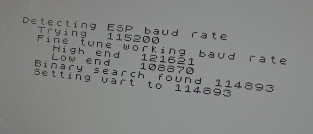
None of them showed installing the correct ESP firmware, what baud rate the Next expects, or even attaching the ESP.
I picked out a board I was confident was working fine, attached it, successfully ran the ESP Updater.
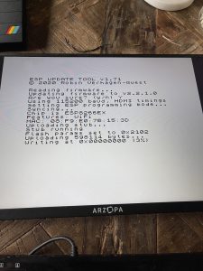
After it confirmed the update, I tried to connect to wifi using the built-in Next menu item …. and failure.
The fact the ESP Updater did its thing suggests also the board was fine therefore I tried and failed all the many ways to get the “driver” to install.
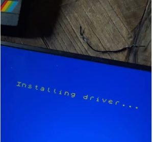
I quickly started to hate this “Installing Driver…” message. There is no indication if anything is happening when it gets stuck there for ages, but other times it quickly quits back to the menu, again with no feedback.
Spoiler alert: Even with everything now ‘working’, it often takes a lot more attempts than you would expect.
To save anyone else the bother I went through, and potentially Future Chris, the key was to NOT update the ESP 01 firmware. Just use whatever your board came with by default. My working firmware is not even listed on the ESP Updater repo …
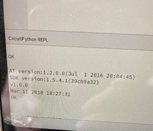
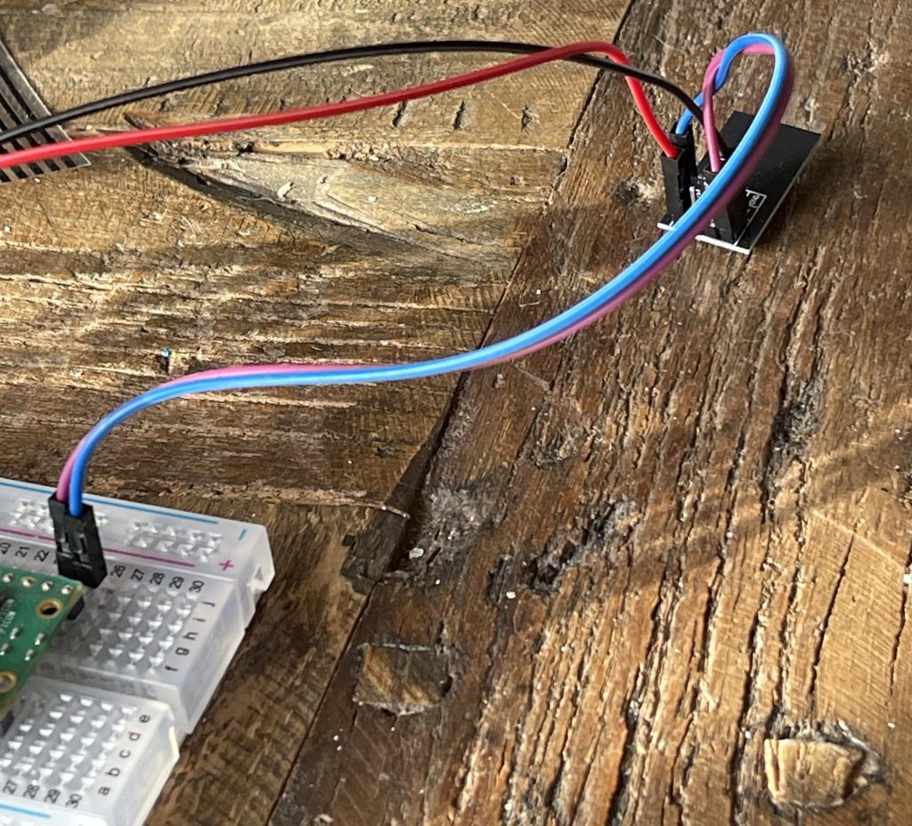
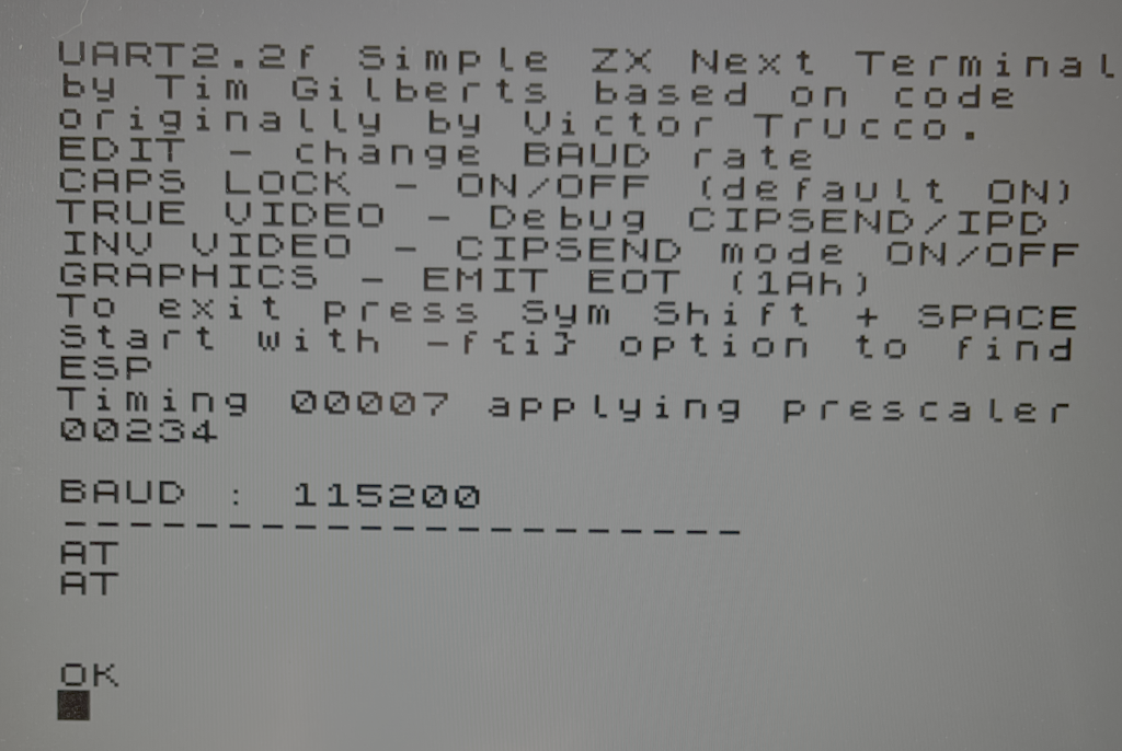
I rummaged around and found another ESP board that had never had its firmware flashed. Using a breadboard I confirmed it was working and responding to AT commands.
CircuitPython Code to Communicate with ESP01 via UART
import board,binascii
import adafruit_pio_uart
# Define the UART pins (example using GP16 for TX and GP17 for RX)
# The actual pins depend on your specific wiring/board configuration.
UART_TX = board.GP16
UART_RX = board.GP17
# Initialize the UART connection
# The baudrate for the ESP01 is typically 115200
uart = adafruit_pio_uart.UART(UART_TX, UART_RX, baudrate=115200)

def send(s):
    uart.write(s+'\r\n')
    print(uart.read(255).decode())
send('AT+RST')
send('AT')
send('AT+GMR')
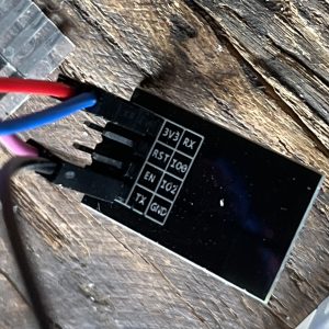
This code allows you to hook the ESP01 up to pins 16 and 17 for UART, and 3.3v and GND.
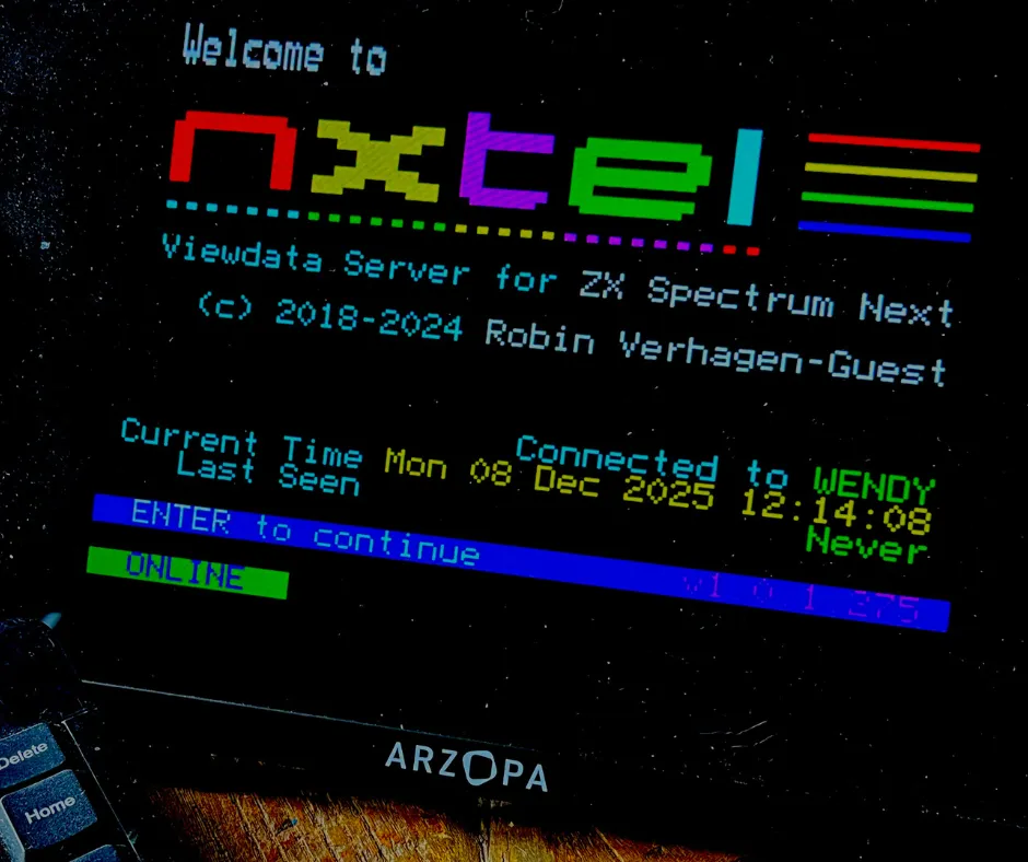
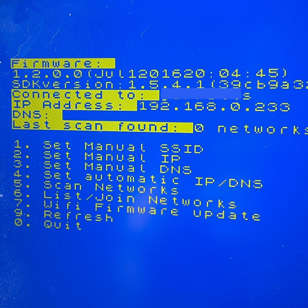
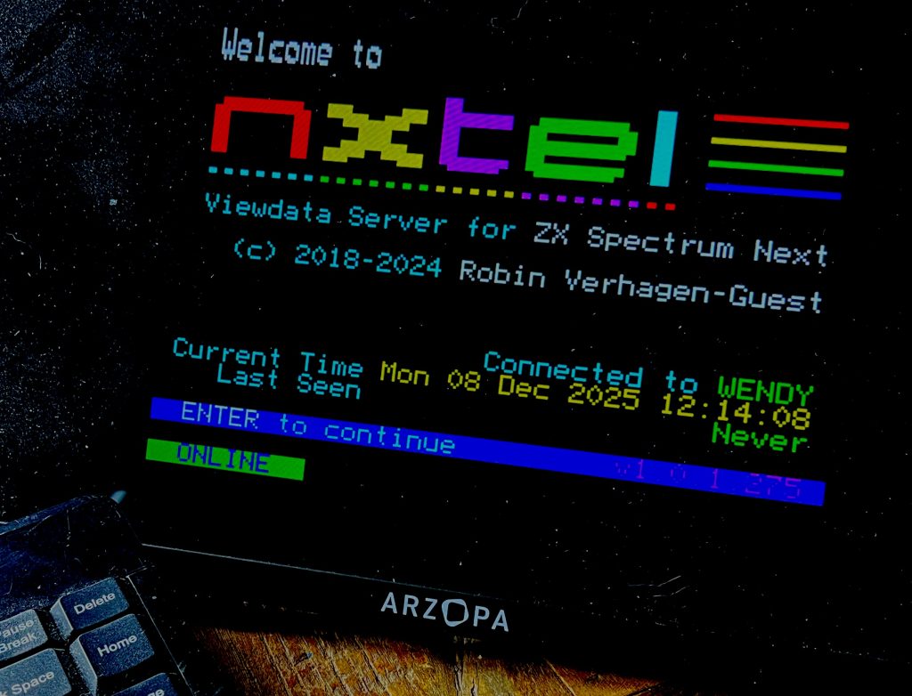
Wifi on the ZX Spectrum Next … Finally!
Again it didn’t work on the ZX Next right away, but I persisted and finally signs of life!
Conclusion
Hope this helps someone else out there! I found it incredibly frustrating but now I am back to having fun with my ZX Next experience rather than regretting my choices.
Seems life might have been easier if a Pi Zero W was used instead of a Pi and an ESP8266, or even an ESP32, but perhaps there is a good reason they went with the little old ESP01.